Tuning Guide
Preparation
When it comes to tuning, the most important step is to prepare and ensure all hardware and sensors are in full working order. That means you know the brand and type (which hopefully you know the specifications) of the following:• MAP sensor (required for tuning)
• AFM (airflow meter), if applicable.
• Injectors (dead time), if aftermarket.
• Ignition coils (dwell time / angle), if aftermarket.
• Wideband o2 controller installed, calibrated (both software and sensor), and ground connected as close and short as possible to PowerFC.
All the above hardware will need correct setting into Apexi PowerFC. Failure to do so may result in problematic tune and impossible-to-resolve-without-full-retune problems.
Here are example scenarios that will cause interesting problems:
• Apexi MAP sensor installed, boost controller enabled (required for MAP sensor based engines), but setting of MAP sensor is still "default".
• Incorrect injector dead (lag) time settings, resulting in either poor or impossible warm-engine start.
• Default AFM setting selected, even though aftermarket AFM is installed.
• Installing MAP sensor _before_ throttle body.
It is important to have correct injector dead time settings as it will allow you to change injectors without spending hours on a full re-tune.
For MAP sensor based tunes, it is best to re-base the correction tune onto the main injection pulse width time table. The reason for this allows graphing this table to further fine-tune it. Not only that, it allows performing injector sizing adjustments and comparision (and utilisation) of tunes from other aftermarket ECUs. The way to do this is:
1) re-base injection correction table
2) multiply injection pulse width table by injector sizing difference. eg: from 440cc to 550cc injectors means multiplying by (440/550) == 0.8
3) multiply acceleration table time amounts by the same number (0.8). Same for decay time.
4) multiply cranking start (ECT) table by injection correction (0.8).
5) set injector correction to 1.000 for each cylinder (or batch injectors) and injector offset to 0.000
For AFM sensor based tunes, adjusting the injection correction setting for each cylinder is recommended. However, adjusting the injector offset time through this same interface is NOT RECOMMENDED and will most certainly result in mistakes and problems. It is best to adjust the main injector dead time table.
Wideband controller and Analog Input
It is recommended that the wideband controller power and ground be connected as close as possible to the PowerFC ECU, preferably to the ECU harness within 30 cm (1 foot) of the ECU connector. This will reduce the possibility of "ground offset" and "ground noise".Some wideband controllers do not internally connect "system ground" and "analog ground" (eg: AEM UEGO), so you will need to connect these two together, and only from there connect to FC-HAKO AN2 or AN4.
One of the WORST things to do is to ground most of your electronics to one place (i.e. the engine block), but ground one device somewhere else (eg: chassis). Not only can this result in ground offsets, it can also create a "path of least resistance" for high currents THROUGH a low-current device. This can result in melted wires when starter currents flow through the gauges.
The following is a list of known default AFR-Voltage conversion values, to be used by tuning software. If possible (eg: Innovate), alter the default values to have lowest multiplier for volts->AFR, eg: Powerdex values is a good option to reduce influence of noise/offset
| WBo2 | AFR-Volts (min) | AFR-Volts (max) | AFR Equation | ||
|---|---|---|---|---|---|
| Innovate LC-1 | 7.35 AFR | 0.0V | 22.39 AFR | 5.0V | AFR = (V*3) + 7.35 |
| AEM UEGO (#2) | 7.3 AFR | 0.0V | 19.2 AFR | 5.0V | AFR = (V*2.375) + 7.3125 |
| HKS / MoTeC | 8 AFR | 0.5V | 20 AFR | 4.5V | AFR = (V*3) + 6.5 |
| AEM UEGO gauge | 10 AFR | 0.0V | 20 AFR | 5.0V | AFR = (V*2) + 10 |
| Neko / SARD | 10 AFR | 0.0V | 20 AFR | 5.0V | AFR = (V*2) + 10 |
| Powerdex AF | 9 AFR | 0.0V | 16 AFR | 5.0V | AFR = (V*1.4) + 9 |
| TechEdge 2J1 | 9 AFR | 0.0V | 19 AFR | 5.0V | AFR = (V*2) + 9 |
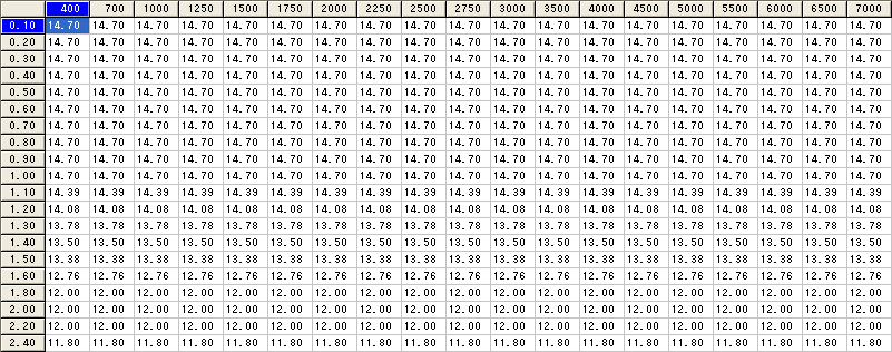
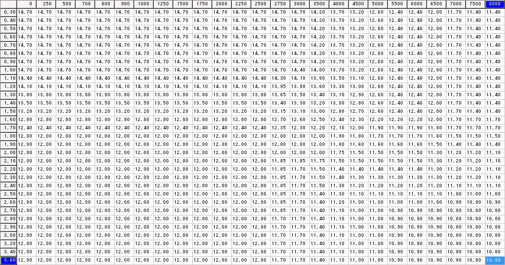
Target AFR table (pressure-based)
It's a good idea to prepare a target AFR table that you can refer to, to lookup AFRs to be expected based on RPM and boost pressure.Running richer past 5000 RPM is not a problem, especially at below maximum boost levels.
For example, Toyota 1JZ-GTE at 10psi to 14psi, needs to run at 11.5 AFR at 4000 RPM onwards.
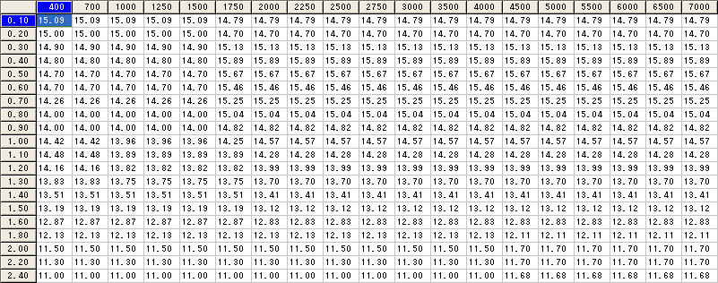
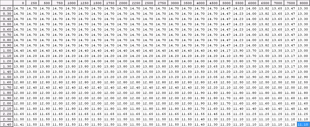
Examples of tables include:
• Toyota 1JZ-GTE 370cc
• Toyota 2JZ-GTE 1000cc
• Nissan RB26DETT 720cc
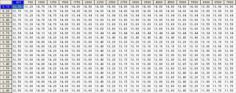
• Nissan RB30DET 800cc
• Subaru WRX STI v5 550cc
• Mitsubishi EVO 9 4G63
Tuning AFM: Injection: Tune Session #1 - maximum vacuum
NOTE: Values in injection volumetric efficiency table is based on 0% reference value, rather than 100%.To convert to PowerFC numbers, add 100.
Other than that, same tuning idea applies.
First step in tuning is to obtain and set the correct vacuum AFRs for various RPMs, which should be done at 80C+ ECT.
For each RPM column (whether 400 RPM intervals or 250-500 RPM intervals), hold the RPM and log for approximately 3-5 seconds. Do not worry if RPM is off by +/- 50 RPM or even by 100. If not logging, note down RPM, engine load, and measured AFR.
You will then be left with the following results:
| RPM | 800 | 1200 | 1600 | 2000 | 2400 | 2800 | 3200 | 3600 | 4000 | 4400 | 4800 | 5200 | 5600 | 6000 |
|---|---|---|---|---|---|---|---|---|---|---|---|---|---|---|
| LOAD | ||||||||||||||
| AFR (act) | ||||||||||||||
| AFR (tgt) | 14.7 | 14.7 | 14.7 | 14.7 | 14.7 | 14.7 | 14.7 | 14.7 | 14.5 | 14.3 | 14.1 | 13.9 | 13.7 | 13.5 |
| offset |
To calculate "offset" = ( [AFR measured] - [AFR target] ) * 7
For each RPM-LOAD value, isolate and highlight higher-than-value cell, to maximum vacuum (minimum load value).
Utilising calculated offset value, add (positive or negative without changing sign) to each set of highlighted cells.
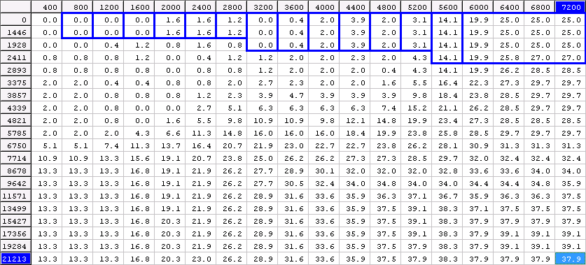
Tuning AFM: Injection: Tune Session #2 - zero vacuum / zero boost
Next stage of tuning is obtaining as-best-as-possible zero vacuum (zero boost) AFR readings. This is the more difficult readings to obtain as variable throttle control is required. 2nd gear is fine for logging.You will then be left with the following results:
| RPM | 800 | 1200 | 1600 | 2000 | 2400 | 2800 | 3200 | 3600 | 4000 | 4400 | 4800 | 5200 | 5600 | 6000 |
|---|---|---|---|---|---|---|---|---|---|---|---|---|---|---|
| LOAD | - | - | - | - | 3373 | 3630 | 3884 | 3886 | 3862 | 3882 | 4076 | 4148 | 4118 | - |
| Boost (psi) | - | - | - | - | 0 | 0 | 0 | 0 | 0 | 0 | 0 | 0 | 0 | - |
| AFR (act) | - | - | - | - | 14.9 | 14.7 | 14.6 | 14.6 | 14.5 | 14.2 | 14.0 | 14.0 | 14.1 | - |
| AFR (tgt) | 14.7 | 14.7 | 14.7 | 14.7 | 14.7 | 14.7 | 14.7 | 14.7 | 14.5 | 14.4 | 14.3 | 14.2 | 14.1 | 14.0 |
| offset | - | - | - | - | +1.4 | +0.0 | -0.7 | -0.7 | +0.0 | -1.4 | -2.1 | -1.4 | +0.0 | - |
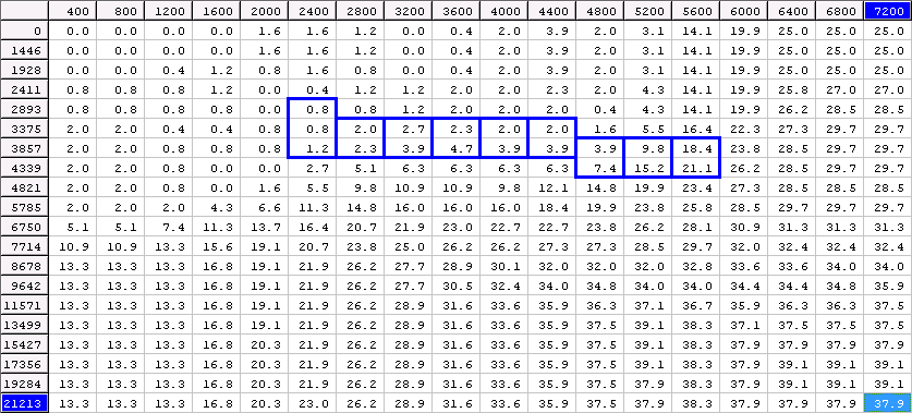
Tuning AFM: Injection: Tune Session #3 - minimum full boost
Next is minimum full boost, which is with the boost controller set to "off". Minimum boost must between 7 psi and 10 psi.If minimum boost within this range cannot be achieved, road-based tuning should NOT proceed.
There are a few ways to obtain AFR readings, depending on RPM range. it is recommended to perform the following:
• 4th gear - 1500 RPM to 3500 RPM
• 3rd gear - 2000 RPM to 4000 RPM
• 2nd gear - 2000 RPM to 6000 RPM
You will then be left with the following results:
| RPM | 800 | 1200 | 1600 | 2000 | 2400 | 2800 | 3200 | 3600 | 4000 | 4400 | 4800 | 5200 | 5600 | 6000 |
|---|---|---|---|---|---|---|---|---|---|---|---|---|---|---|
| LOAD | - | - | - | - | 5623 | 6620 | 7769 | 7572 | 7724 | 7763 | 8157 | 8297 | 8237 | |
| Boost (psi) | - | - | - | - | 1 | 5 | 7 | 7 | 7 | 7 | 7 | 7 | 7 | - |
| AFR (act) | - | - | - | - | 14.9 | 14.1 | 13.3 | 13.4 | 13.3 | 13.4 | 13.4 | 13.0 | 13.1 | - |
| AFR (tgt) | 14.7 | 14.7 | 14.7 | 14.7 | 14.7 | 14.1 | 13.2 | 13.2 | 13.2 | 13.1 | 13.0 | 12.9 | 12.8 | 12.7 |
| offset | - | - | - | - | +1.4 | +0.0 | +0.7 | +1.4 | +0.7 | +2.1 | +2.8 | +0.7 | +2.1 | - |
For each RPM-LOAD value, isolate and highlight group of cells.
Utilising calculated offset value, add (positive or negative without changing sign) to each set of highlighted cells.
Tuning AFM: Injection: Tune Session #4 - interpolate and validate results
The next part is interpolation. Cells must be identified in each of the 3 sessions to determine range of cells to interpolate.Usually it will be the range of cells that were not modified plus one cell on either end of the range that were modified by offset / addition.
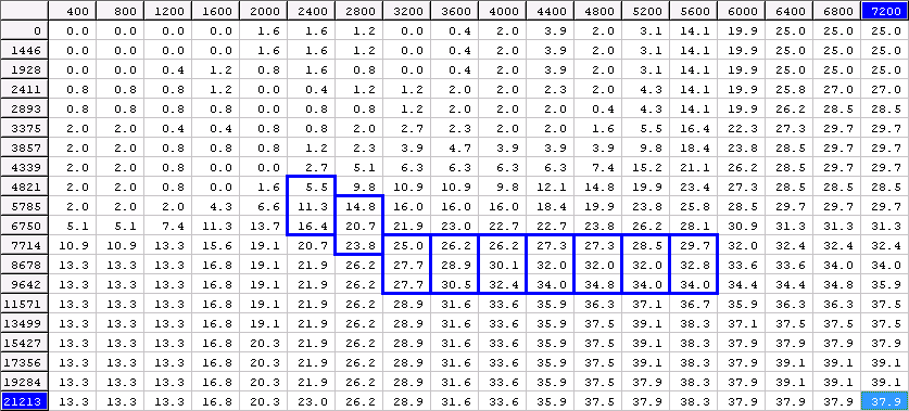
Tuning AFM: Injection: Tune Session #5 - increasing maximum boost
Increase maximum boost by 1.0 psi, and perform the same logging and adjustments to the table.No interpolation is required _above_ minimum full boost levels.
Tuning AFM: Ignition: Tune Session #6 - minimum full boost
Tuning ignition can be performed during injection tuning if knock levels above 10 are detected.Otherwise, a separate ignition-only tuning session should be performed.
It is best to set knock warning light to 20 or 30. This will give the driver an indictor when to halt the tune, to avoid sustained engine damage
For knock level between 5 and 10, ignition should be reduced by -1.
If knock still occurs at the same level having reduced ignition by 3 degrees, run richer.
If knock level is below 3, increase ignition by +1.
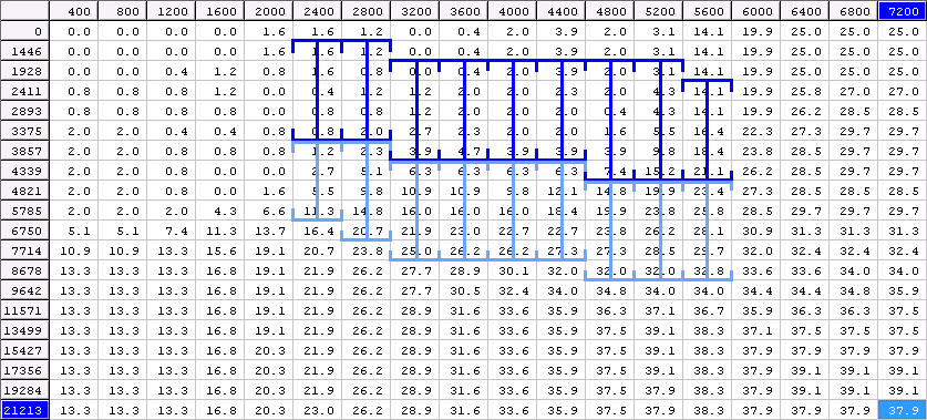
You will then be left with the following results:
| RPM | 800 | 1200 | 1600 | 2000 | 2400 | 2800 | 3200 | 3600 | 4000 | 4400 | 4800 | 5200 | 5600 | 6000 |
|---|---|---|---|---|---|---|---|---|---|---|---|---|---|---|
| LOAD | - | - | - | - | 5623 | 6620 | 7769 | 7572 | 7724 | 7763 | 8157 | 8297 | 8237 | |
| Boost (psi) | - | - | - | - | 1 | 5 | 7 | 7 | 7 | 7 | 7 | 7 | 7 | - |
| Ignition | - | - | - | - | 25 | 22 | 19 | 19 | 19 | 19 | 18 | 18 | 17 | - |
| Knock | - | - | - | - | 1 | 1 | 2 | 2 | 4 | 5 | 7 | 6 | 3 | - |
| Adjust | - | - | - | - | 0 | 0 | 0 | 0 | -1 | -1 | -1 | -1 | 0 | - |
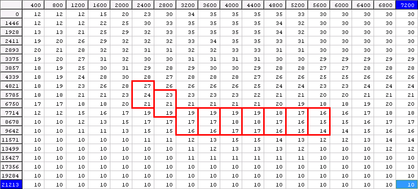
For each RPM-LOAD value, isolate and highlight group of cells.
Utilising adjustment value, add (positive or negative without changing sign) to each set of highlighted cells.
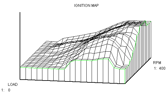
Graph the ignition table in 3D to identify non-smooth ignition regions.
Once ignition tuning session is completed, reduce ignition by 1 under boost region after 4000 RPM.